Construction of a new eight megalitre potable water above-ground tank to serve new housing developments.
Background
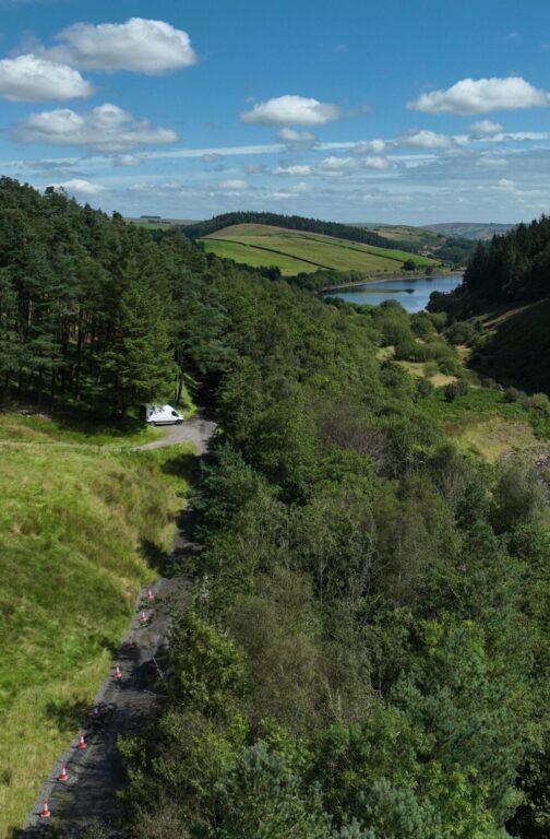
Bourn Reservoir is an above-ground reservoir complex located approximately five miles outside Cambridge, England. Only one tank was still operational after the other two were removed from service due to natural degradation.
A new tank was required to meet demand from large-scale developments in the supply area. A review was conducted to ascertain the total water volume required, revealing the need for an additional 8Ml of storage on top of the capacity of the remaining tank by the summer of 2022.
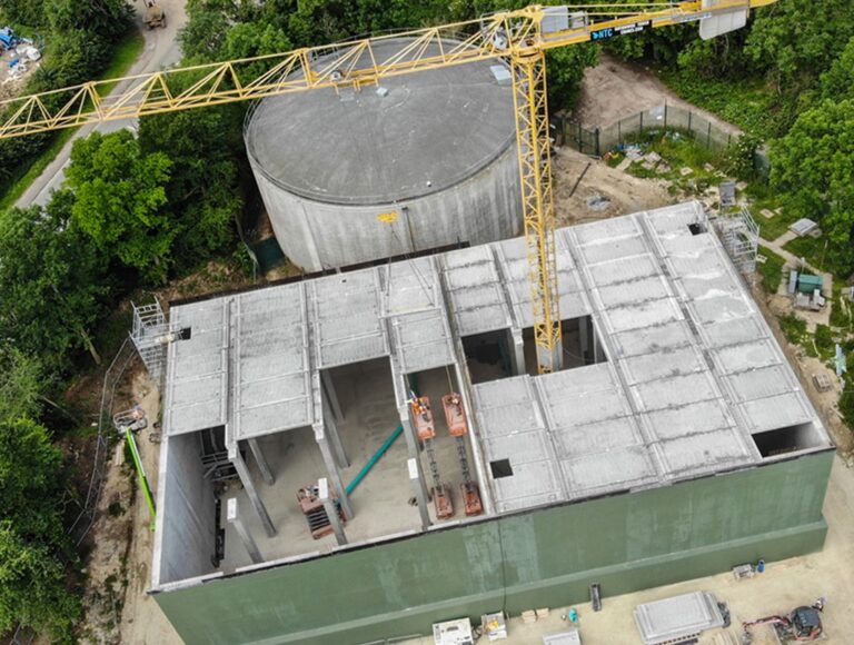
Stonbury was contracted to demolish the disused circular prestressed tank in 2020, whilst the other remained in service, and returned in 2021 to begin the construction of a new 8Ml concrete tank next to the operational reservoir.
Project team
The project was delivered for Cambridge Water, as Client, by Stonbury, direct-delivery water sector specialist contractor, as Principal Contractor and Principal Designer, with Mason Clark Associates as Designer.
Scope
A summary of the works undertaken is as follows:
- Disconnection and demolition of the old Reservoir No 2
- Ground investigation works and tree removal
- Groundworks
- Design of new concrete tank
- Construction of new tank, drainage and connecting pipework
- Installation of MEICA elements
Site description
The Bourn reservoir site is a small, spatially-constrained compound that originally contained Reservoirs 2 and 3 but solely contained Reservoir 3 after the preparatory demolition of Reservoir 2 in 2020. Land owned by the farmer adjacent to the site was utilised for the site compound which housed welfare units, a storage area, and turning space for vehicles and machinery. The land was returned after the programme was complete.
Project challenges
The build possessed several unique challenges due to constraints on time and space. The planning application review period was extended for further environmental assessment as part of the Tree Retention Scheme, which introduced significant time constraints to the programme. Pro-active action was taken to minimise delay, and a revised foundation plan was submitted accounting for the proximity of tree roots and including provision of a perimeter root barrier trench for additional protection. Planning permission was granted in October 2021, leaving under a year to complete the project by the summer of 2022.
Innovative pre-construction planning was required to overcome the issues posed by the constrained size of the operational area. As the site footprint dictated a tank shape that was non-optimal for water flows, a computational fluid dynamics (CFD) analysis was completed to identify a ‘best practice’ design to reduce dead spots and protect water quality. As the new tank footprint was partially on virgin ground and partially on ground where the previous structure had stood, there was a risk of differential settlement. To mitigate this risk, a tailored ground investigation was conducted to obtain data for a predictive settlement analysis to inform the engineered fill design and ensure a robust outcome.
Design
Mason Clark Associates was responsible for the civil and structural design of:
- The reinforced concrete twin-compartment reservoir, excluding the detailed design of precast roof slab panels
- The reinforced concrete valve house
- The surface, underdrainage, and foul water drainage systems
- The external steel roof access staircase
The client stipulated that each cell would require the following features:
- Opposed high-level inlet and a low-level outlet, connected to the existing network
- Automated control valves
- Combined metered washout/overflow pipe
- Overflows with sufficient capacity to take design inflow whilst maintaining sufficient freeboard to the soffit of the roof
- Washouts, sized suitably to enable the drain down of each cell over a 24hr to 48hr period without causing flooding to surrounding watercourses
- Sufficient ventilation to ensure that each cell is not over-pressurised during filling or a vacuum created during drawdown
- Access doors and hatches to meet LCPB 4 rating and SEMD requirements
- All necessary ductwork for telemetry and security cabling
- Mains alterations to accommodate the new reservoir
- Arrangements for taking compliance samples
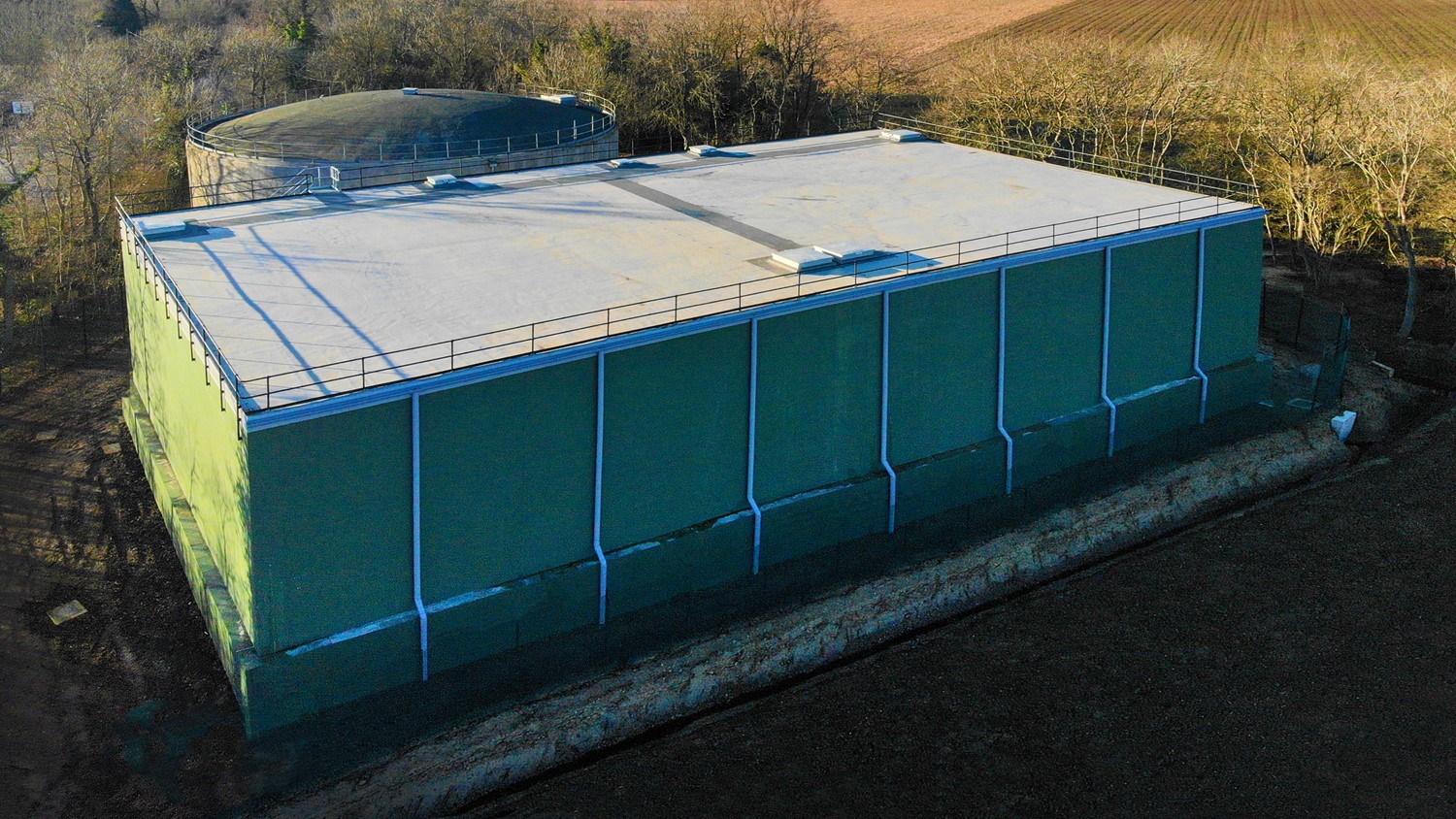
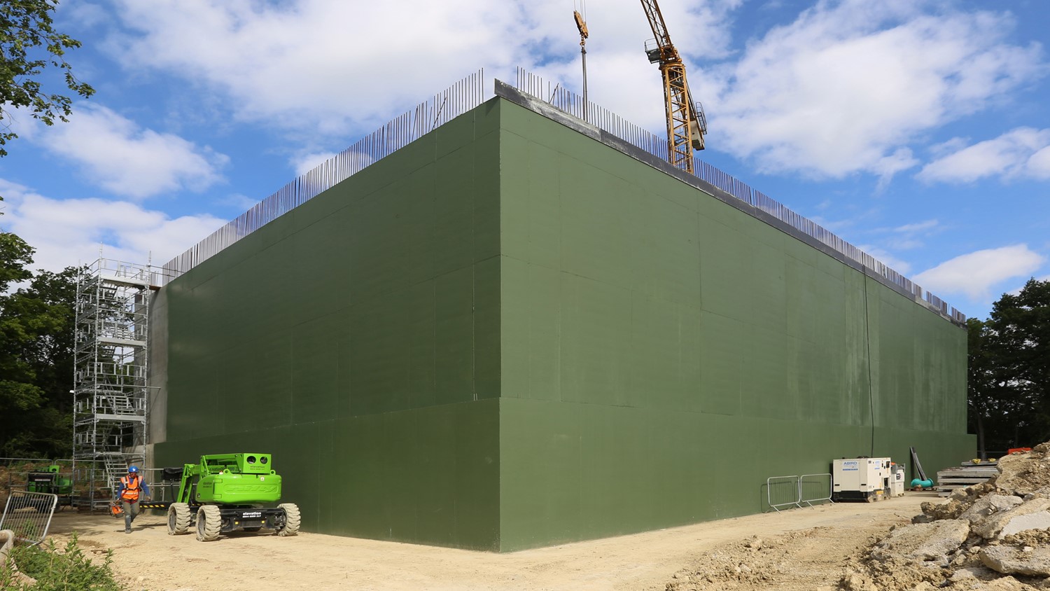
The proposed tank was to have an approximate footprint of 850m2 and operate with a top water level of 79.2mAOD (ground level is approximately 71.4mAOD). The inlet was to be connected to the pumping main, whilst the outlet connected to the same main as Bourn Reservoir 3 so that they would operate hydraulically together. The placement of inlet and outlet valves, baffle walls and weir boxes were designed in accordance with results from the CFD analysis.
Addressing the drive to build assets with lower embodied carbon and to reduce the length of the programme, the design incorporated the use of pre-cast concrete roof slabs in addition to conventional in-situ pour concrete. This was preferred to a fully pre-cast solution due to the risk of perennial ingress issues at pre-cast joints. This would help to reduce embodied carbon by approximately 10% compared with a traditional build and make 48-week programme possible.
The structural elements of the reservoir and pipework were to have a minimum design life of 50+ years, and 20+ years for all other elements. All structural and geotechnical design was in accordance with the relevant section of the Eurocodes, and all concrete elements were designed with a water-tightness classification of 1. All work was designed to be carried out in accordance with the latest CESWI, WIMES and Cambridge Water general engineering specifications and to meet DWI requirements for potable water storage units and the current SEMD guidance.
Environmental management
A Project Site Environmental Assessment sought to register and mitigate site-specific environmental impacts such as noise, land and watercourse pollution, waste materials and damage to local ecology. Identified environmental risks were controlled through measures detailed in Risk Assessments and Method Statements.
A preliminary ecological appraisal was undertaken during the pre-construction phase to determine the presence of dedicated nature conservation sites and protected species in proximity to the site. The site was not within or near an SSSI. No notable plant species were identified but some notable animal species were. Recommendations were provided based on the ecological mitigation hierarchy to avoid, mitigate, and compensate during and after the programme.
Health and Safety
A detailed H&S File was prepared for the client. During construction, special site-specific Health and Safety considerations were planned, managed and monitored using a variety of means, including:
- Site-suitable PPE
- Approved RAMS
- Vibration, noise and CoSHH assessments
- Daily Point of Work Risk Assessments (PoWRAs)
- Suitable barriers and safety signage
- Obstructions or trip hazards protocol
- Agreed working hours and strict adherence to quiet periods
- Asbestos protocol
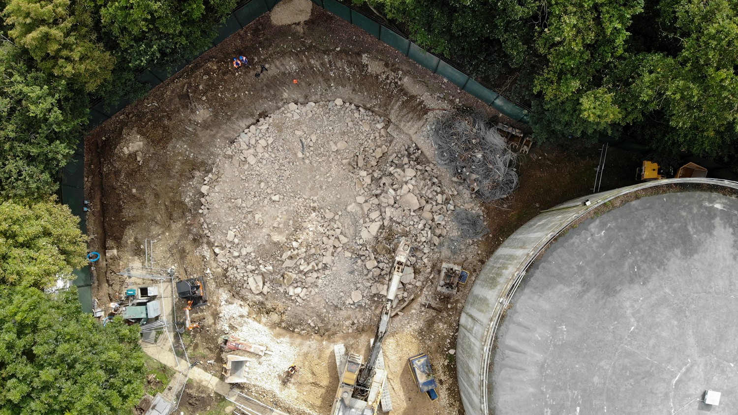
Demolition
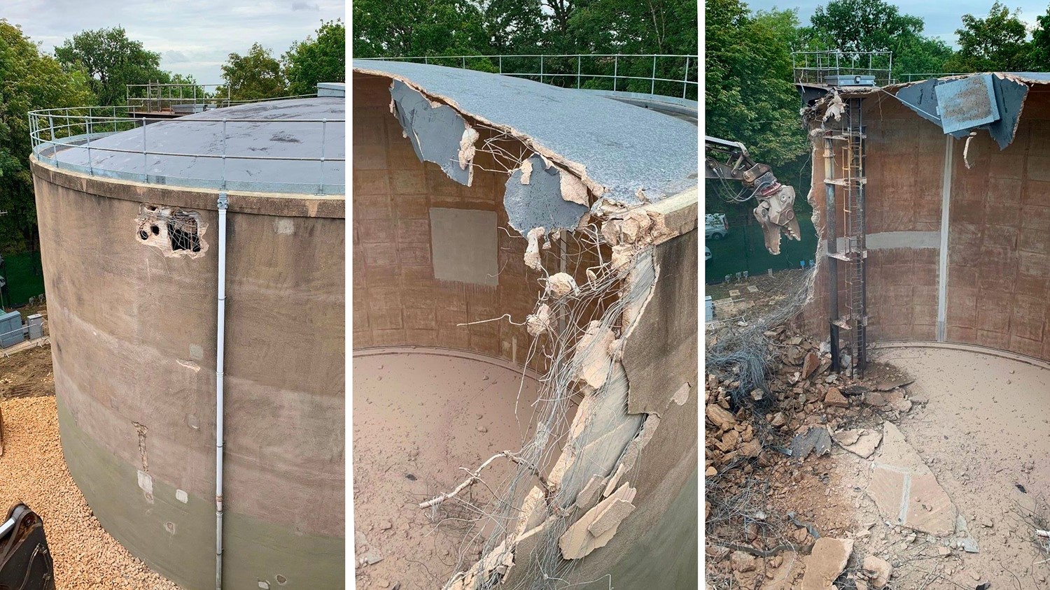
In 2020, existing services into Reservoir 2 were disconnected and removed in preparation for tank demolition. Due to the spatial constraints of the site, demolition was carefully planned with an appropriate methodology to mitigate risk to the live operational tank. An excavator was employed to demolish the roof, with an attached claw to cut the concrete walls into small vertical sections. All broken material was pushed into the middle of the tank during demolition to protect the adjacent asset. Once demolished, material was removed from site.
Site preparation
A site compound was constructed for offices and welfare facilities. This area also had space for limited parking, temporary materials storage and a turning area for construction vehicles. Heras fencing was erected on the boundary of the compound area and construction warning notices were posted at the site entrance gates.
To prepare the area for the reservoir, the locations of services were pre-determined using a combination of existing service drawings, site knowledge and CAT scanning using a signal generator followed by hand-excavated trial holes.
Construction
Base construction
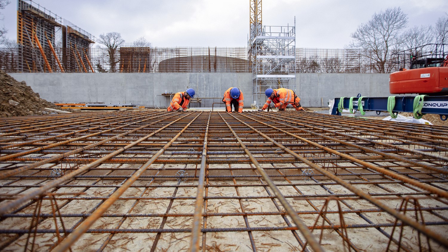
The site for the new tank was excavated, removing spoil and saving a small stockpile for backfilling. Old balancing pipework was removed and the existing pipes were capped so that they could be reconnected upon project completion. Underdrains were installed. Fill-to-base was completed in accordance with the design informed by the predictive settlement analysis. The area was levelled, filled with type 1 material to the specified formation level and rolled. A 50mm concrete blinding base was poured from a dumper and levelled by hand.
Concrete square bars were laid by hand to support the reinforcement steel placed directly on the blinding slab and tied, ensuring correct laps in accordance with the design. Timber formwork was levelled using a laser level placed on each end. Once this was braced, the floor was completed in four separate concrete pours. The sump was poured at the same time using a concrete pump and vibrated constantly as the concrete entered the reinforcement.
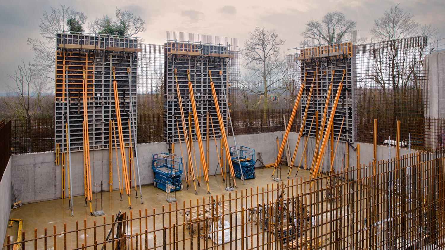
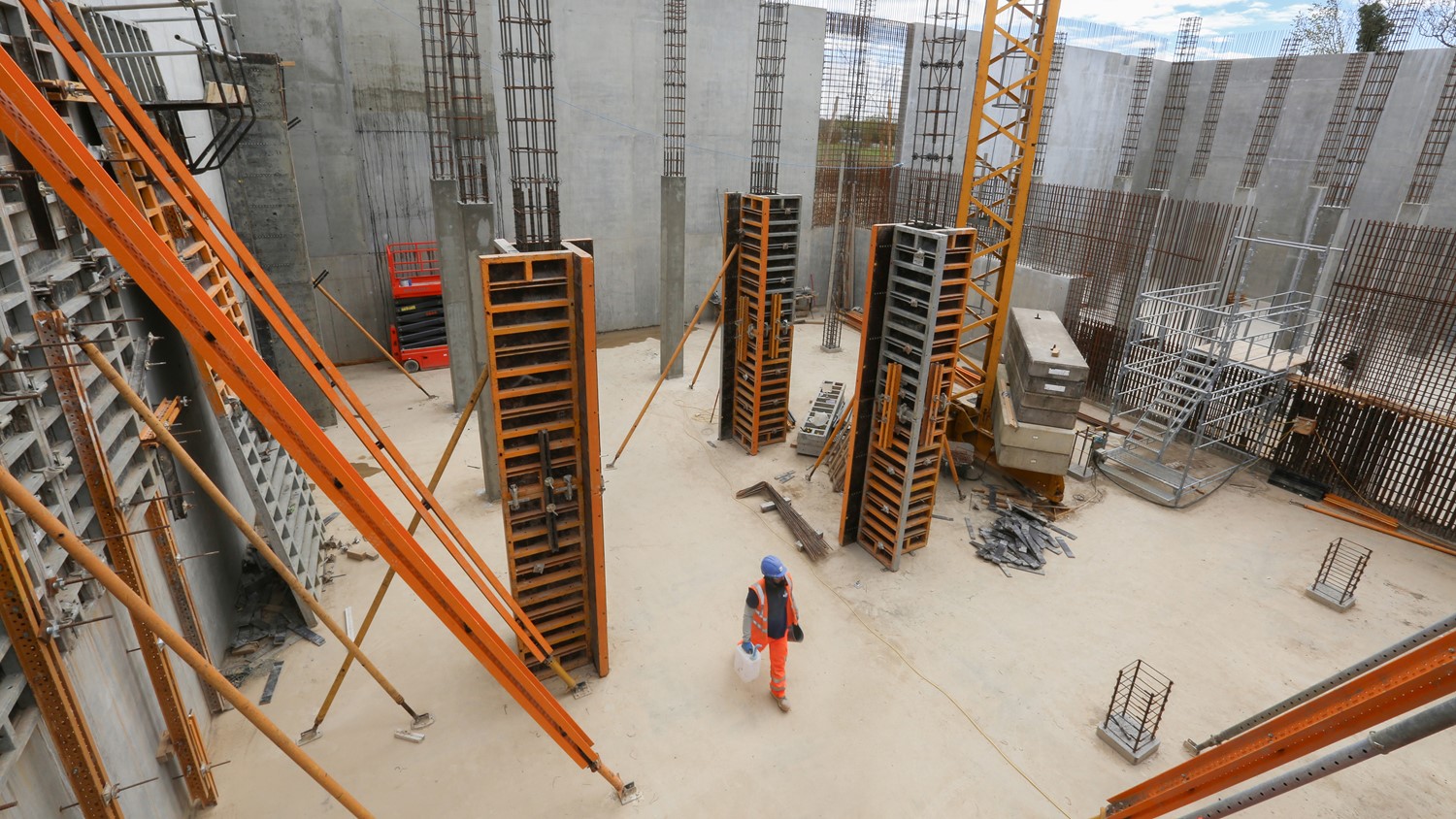
Wall construction
A panel system with film-faced plywood was built for the wall and column formwork according to drawings. Completed shutters were lifted into place using an excavator for the 3-metre-high lower walls and a tower crane for the 7.8-metre-high upper walls. Reinforcement cages were fabricated on the ground and lifted into position with a tower crane to minimise working at height. Inner shutters were held in place with push-pull props drilled and fixed to the base slab. Outer shutters were fixed using Dywidag bolts and tie bars on the outer edge. Timber stop ends were fixed to the ends of the shutters. The concrete was poured in sections and vibrated as filling proceeded, employing both external formwork vibrators and 10m long internal vibrators to achieve the required concrete finish. Shutters were lifted, cleaned and re-positioned for each 5-metre-wide pour section. Once all sections were full, laser levels were used to check levels and tops were floated off.
Pipework
At this stage, trenches were excavated for overflow and outlet pipework. Outlet pipework was installed first and connected to the existing valves. A flow meter was installed in line and a chamber was built around it. Pipes were capped prior to installation, chlorinated and bagged off to prevent contamination. Once installed, pipes were pressure-tested and the trenches were filled with stone and backfilled in layers.
The flow meter chamber was excavated using a 5-tonne excavator and concreted with formwork and vibration. A Technocover lid was drilled and fixed to the cover slab and a galvanised ladder was affixed to gain access to the flow meter. Ducting was installed for the control panels and mains power. Once the main walls were complete, internal access and pipework were installed.
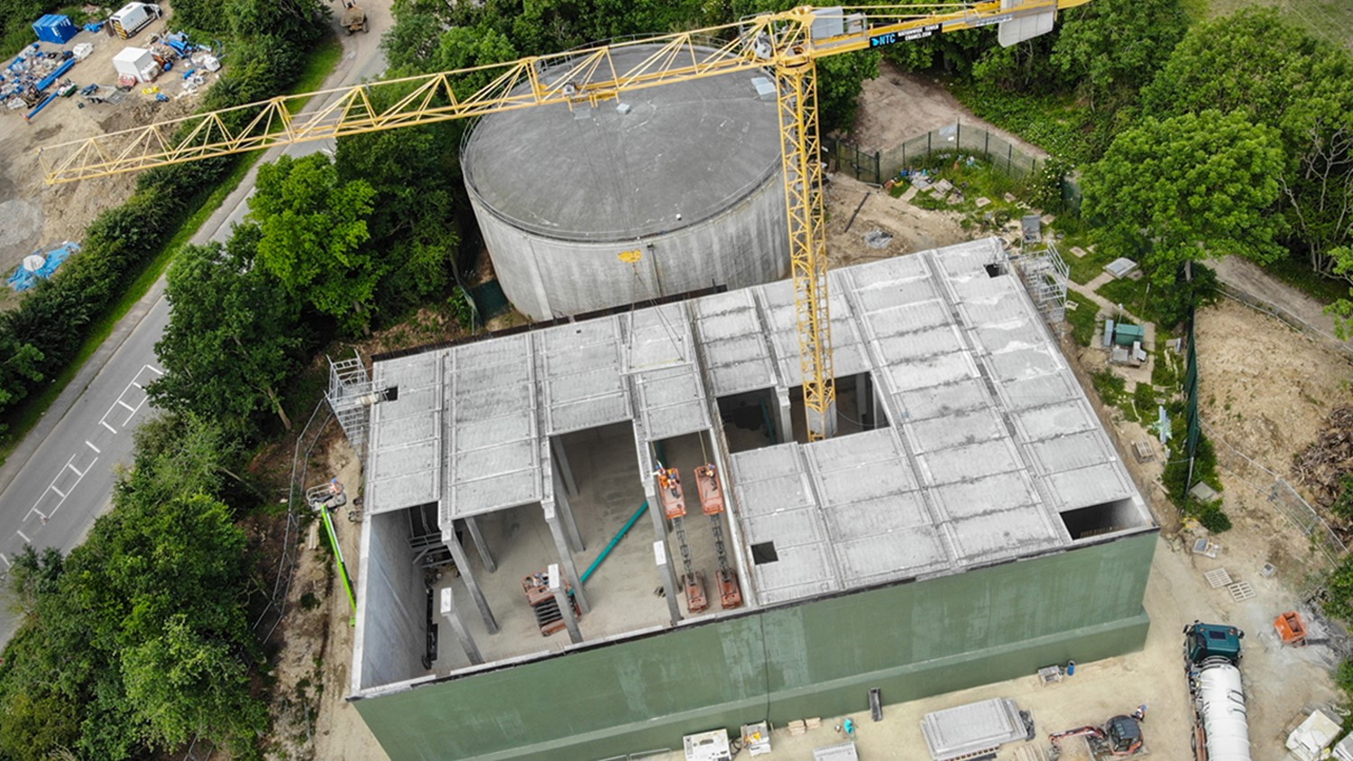
Roof construction
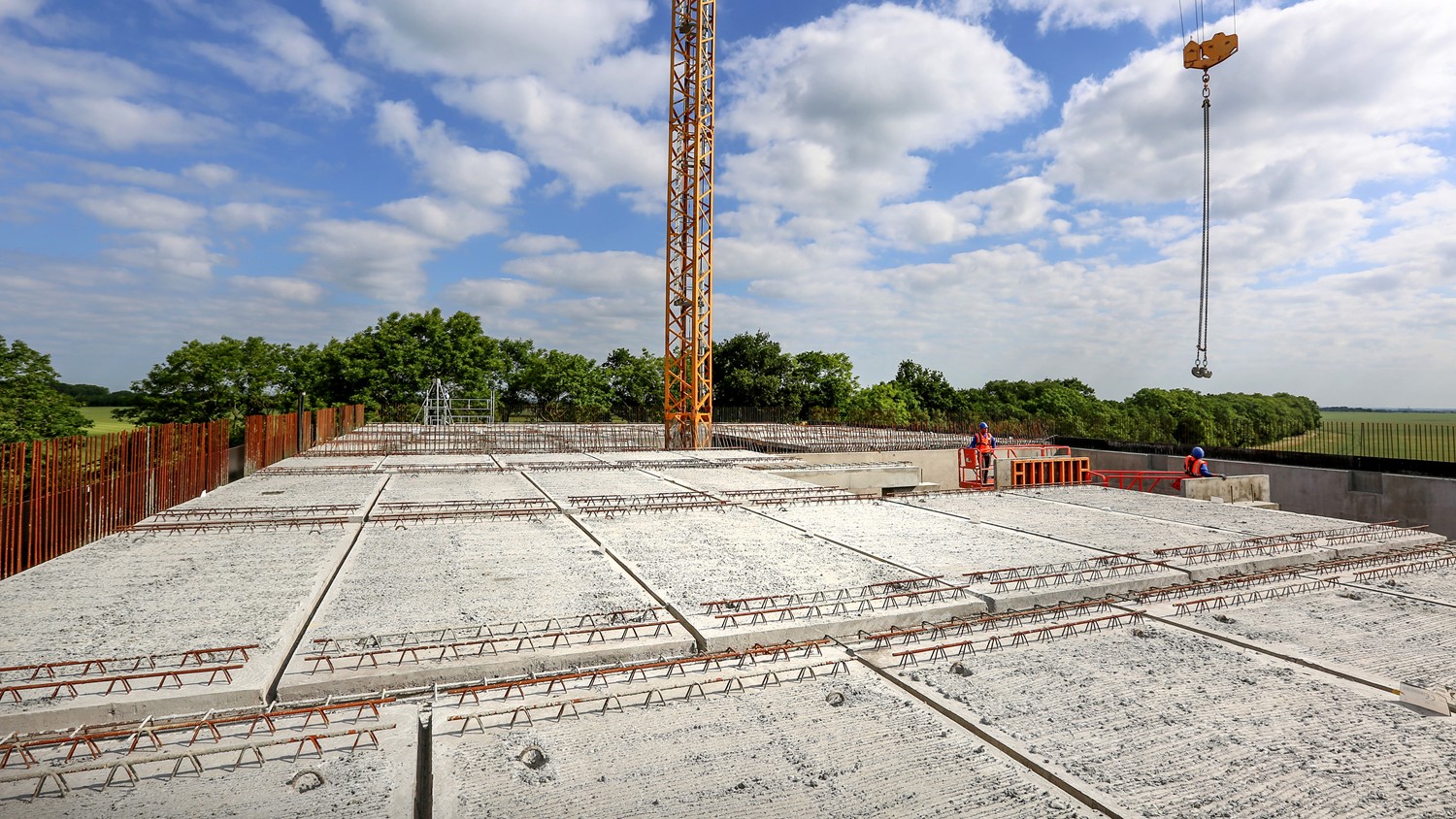
To construct the roof, 30 steel beams were lifted onto the reinforcement cage using a tower crane with two operatives in scissor lifts to guide them. A tower crane was then used to manoeuver 86 150mm precast concrete panels to create the roof slab.
The panels were attached to the crane with a four-legged chain and lifted into position, guided by operatives in scissor lifts. Once all the panels had been placed on the roof, the joints were infilled with concrete ready to take a 150mm structural concrete screed and Lytag levelling screed, laid with a fall of 1:80 front to back to allow water to run off from the roof.
The outer walls were washed, spray-primed and painted with anti-carbonation green camouflage paint to protect the concrete from weathering and reduce visual impact from the road. A waterproof liquid seamless coating system was applied to the tank roof with anti-slip walkways. Finally, a permanent exterior access staircase and perimeter handrailing were installed.
Leak tests
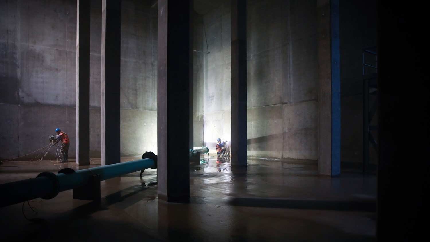
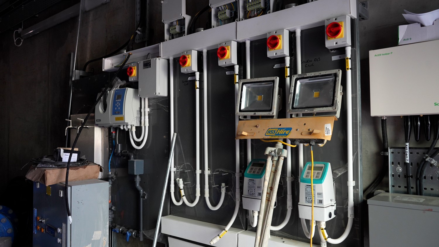
The reservoir was filled with water and underwent a seven-day drop test to ensure there were no leaks. Once successfully passed, the tank was drained for a final inspection, clean and chlorination. Outside, attenuation drainage was installed and security fencing was erected. MEICA elements were installed by IWS, a specialist contractor. Their scope included a full ICA upgrade of the site, reservoir level monitoring, electronic security and electrical distribution for the site.
Post-construction
Earlier CFD modelling and ground investigations had indicated the requirement to fill both cells immediately upon commissioning and keep them simultaneously in use for the first six months of operation to ensure ground was consolidated following the build. As a consequence, the inspection of the internal dividing wall could not be completed during the asset handover. To provide assurance to the client, Stonbury arranged to undertake a further inspection after six months, which confirmed integrity.
Conclusion
The project was completed according to programme without delays or health and safety incidents. The new tank was connected to the network in October 2022 and will increase water security within Cambridgeshire for decades to come.