Increasing stormwater capacity to reduce storm overflow discharges
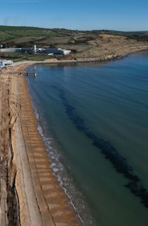
According to the Environment Agency, over 450,000 monitored stormwater discharge events occurred in England last year. To address this issue, the government’s Discharge Reduction Plan aims to cut the number of spill events by increasing the stormwater volume allowance – the amount of stormwater that must be retained on-site before being released into nearby water bodies – at wastewater treatment works throughout the country. The project in the Midlands formed part of a £27.8m Storm Overflow Discharge Programme to increase stormwater storage capacity across 41 of its sites across the county.
Background
Stonbury’s client’s Storm Overflow Discharge Programme programme ensures compliance with the mandated allowances and supports their commitment and broader initiative to reduce storm overflow discharges at wastewater treatment sites. The Storm Tank Project involved the installation of a new 110m3 storage tank, will reduce stormwater discharges near a local Nature Reserve, protecting local water quality, supporting the area’s natural environment and increasing biodiversity in the surrounding lakes. The storm tank build formed the last in a programme of ten that Stonbury delivered as part of the programme.
Site description
Surrounding the site are industrial and residential areas to the south and west, and woodland and arable land to the north and east. The nearby Local Nature Reserve is present to the immediate north of the site, which consists of plantation woodland with three large areas of open water, the largest of which has an extensive area of reed bed. The reed bed is one of the largest in Derbyshire and this, with the surrounding mudflats, provides ideal conditions for over 200 bird species. The Treatment works site services many houses and businesses in the area. The new tank was to be installed in an area comprising semi-improved grassland which is of limited ecological value. The wider site supports areas of additional grassland, woodland, scrub and a small area of wet woodland habitat.
Project scope
A summary of the works delivered is as follows:
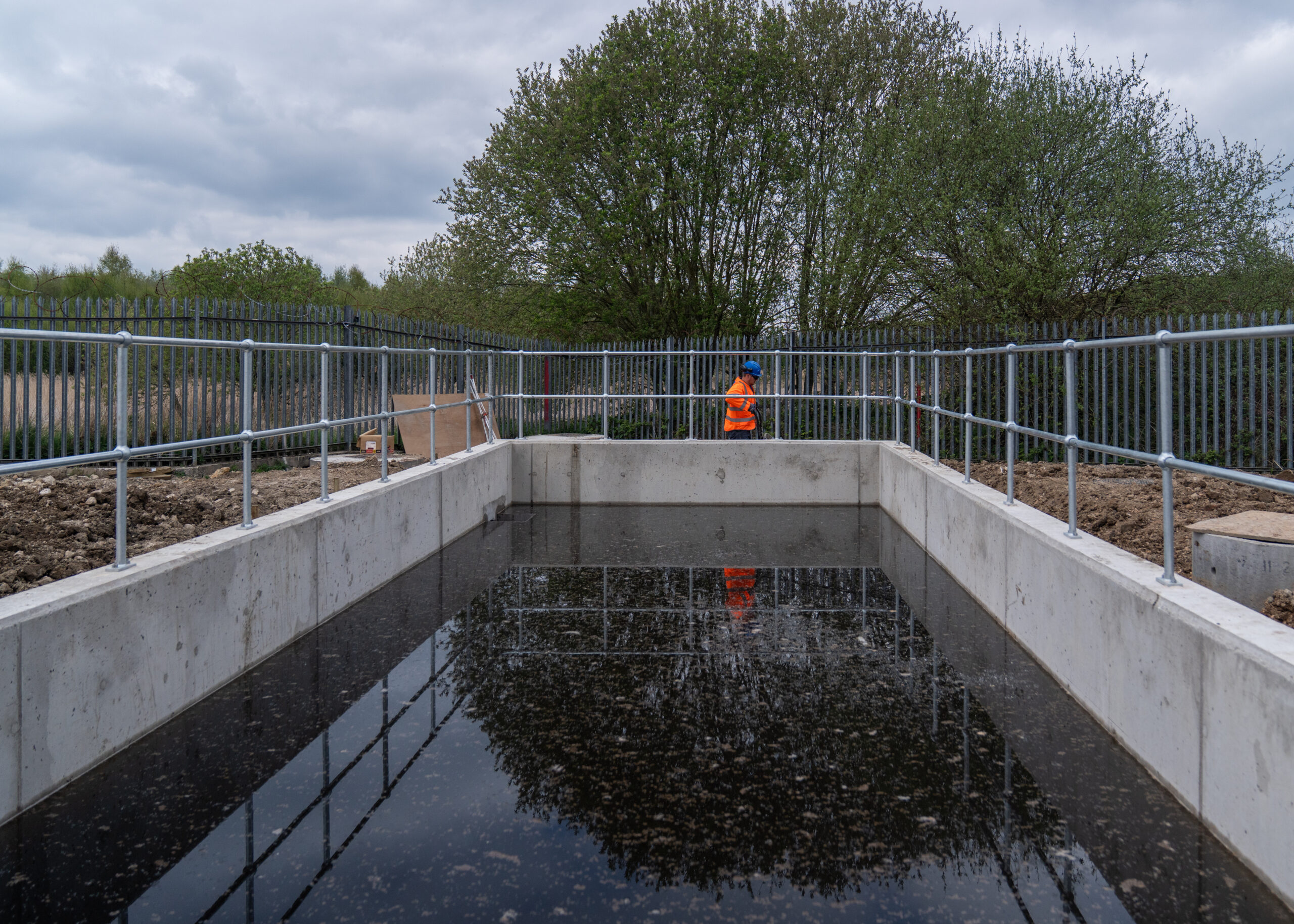
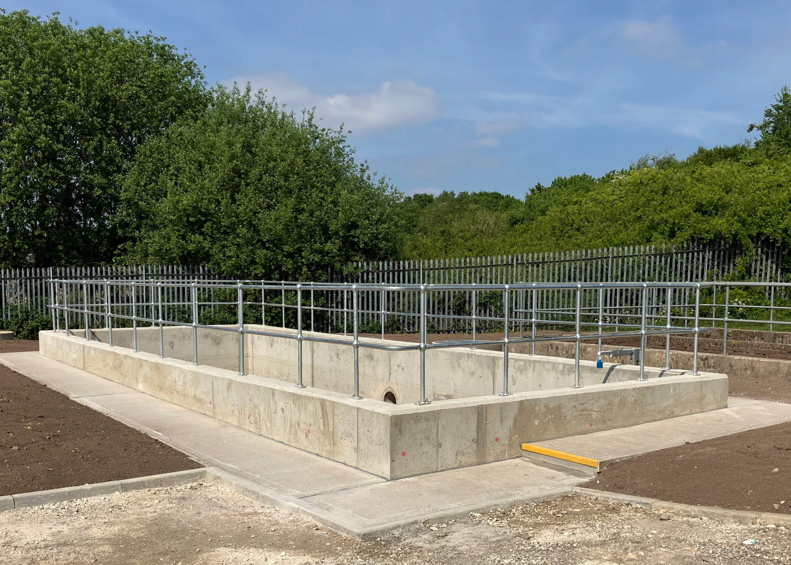
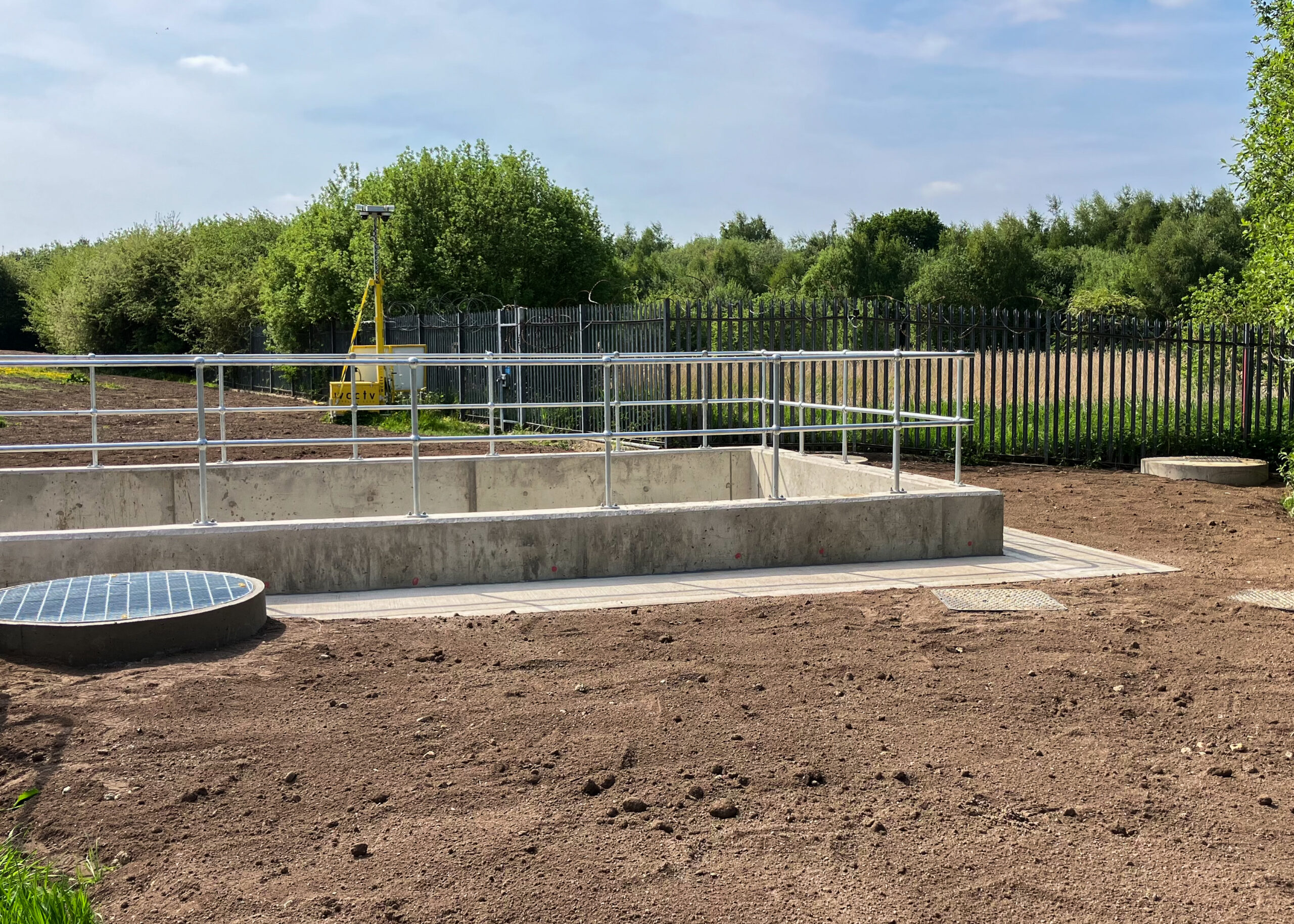
- A reinforced concrete storm tank of internal dimensions 13m x 4.6m x 2.42m average depth.
- 5 (No.) 1200mm diameter precast concrete chambers and a 450mm diameter storm overflow twin wall HDPE storm overflow diversion pipe 15m long.
- 400mm diameter ductile iron storm overflow inlet and outlet pipe to new storm tank.
- 400mm diameter Althon HDPE/SS 316L penstock in storm tank inlet chamber.
- 150mm diameter ductile iron storm tank drain down pipe with a 1200mm diameter precast concrete chamber 2.5m deep.
- 150mm diameter HDPE flap valve fitted inside Storm Tank No. 3 at the end of the new drain down pipe.
- Stainless steel weir box sized 600mm x 450mm x 450mm within the storm tank and a stainless steel weir wall 800mm x 650mm inside the inlet chamber.
- An ultrasonic transducer head with a control unit in the site control building with new overflow spill to the river telemetry alarm and associated cabling.
- Modifications to PLC to create a spill to river alarm from the new storm tank (Storm Tank No. 4) and a new storm tank page on the HMI.
Habitat management
An ecological appraisal was undertaken during the pre-construction phase to determine the presence protected species on and immediately surrounding the construction site. This included a site walkover & desk top survey carried out by the ecologist to identify/consider if any of the following – fauna, amphibians, reptiles, birds, bats, badgers, and any other notable and legally controlled species. Results revealed a small number of marsh orchids (Dactylorhizasp.) were present within the grassland immediately south of the proposed new tank location. While risk was low, to mitigate damage, the report stated that if the area was to be disturbed, the orchids should be removed and translocated by an ecologist to the adjacent grassland outside of the footprint of works, after a thorough assessment of the receptor area by the ecologist.

Storm Tank: Supply chain – key participants
- Principal designer & contractor: Stonbury Ltd
- Designer: Mason Clark Associates
- Ecological appraisal: Habitat Works
- Shuttering : MGF Ltd
- Concrete: Cemex
- MEICA installation: CEMA Ltd
- Penstocks: Althon
Construction
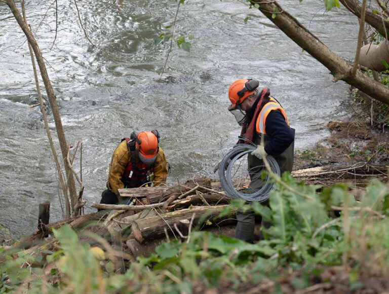
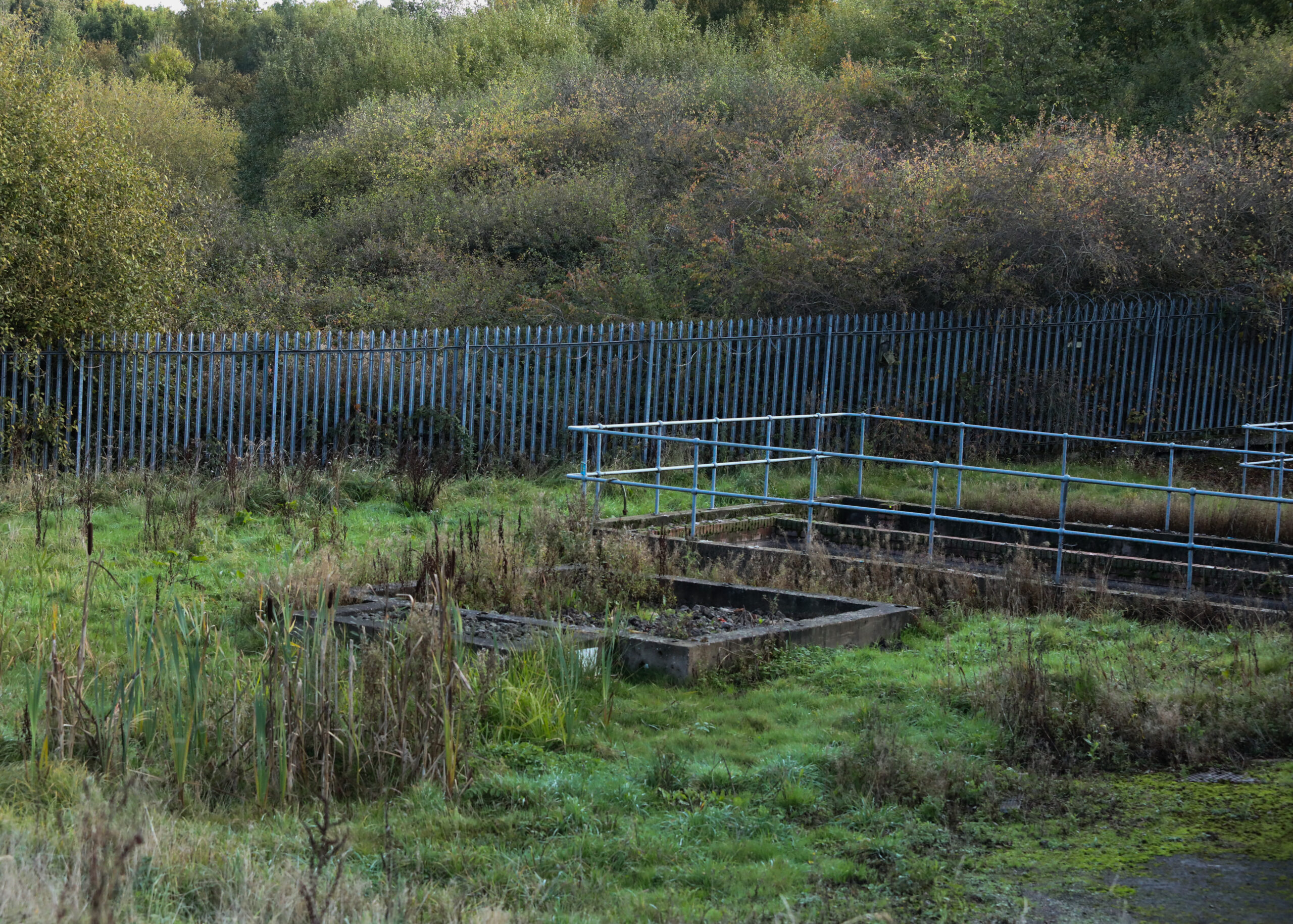
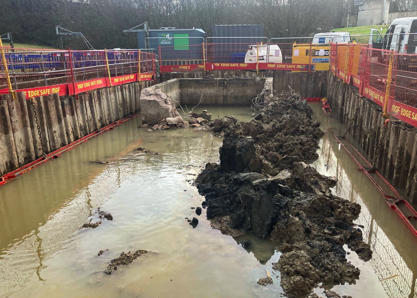
An overflow diversion was installed and air tested in accordance with the client’s Engineering Specifications to allow works to begin. Once this was in place, the two redundant concrete humus tanks were demolished. Waste materials were crushed on site and reused as hard core for the new storm tank base to reduce waste and carbon emissions.
The diversion pipe and chambers were constructed first so that storm overflows could be re-routed around the proposed excavation, with the end connections installed during dry weather periods.
The location for the new tank (Storm Tank No. 3) was prepared by installing temporary works which allowed the excavation for the new tank to take place. Sheet piles and frames were driven into the ground using a 13t excavator equipped with a piling hammer, providing support for the existing grounds. The team then demolished the redundant tanks.
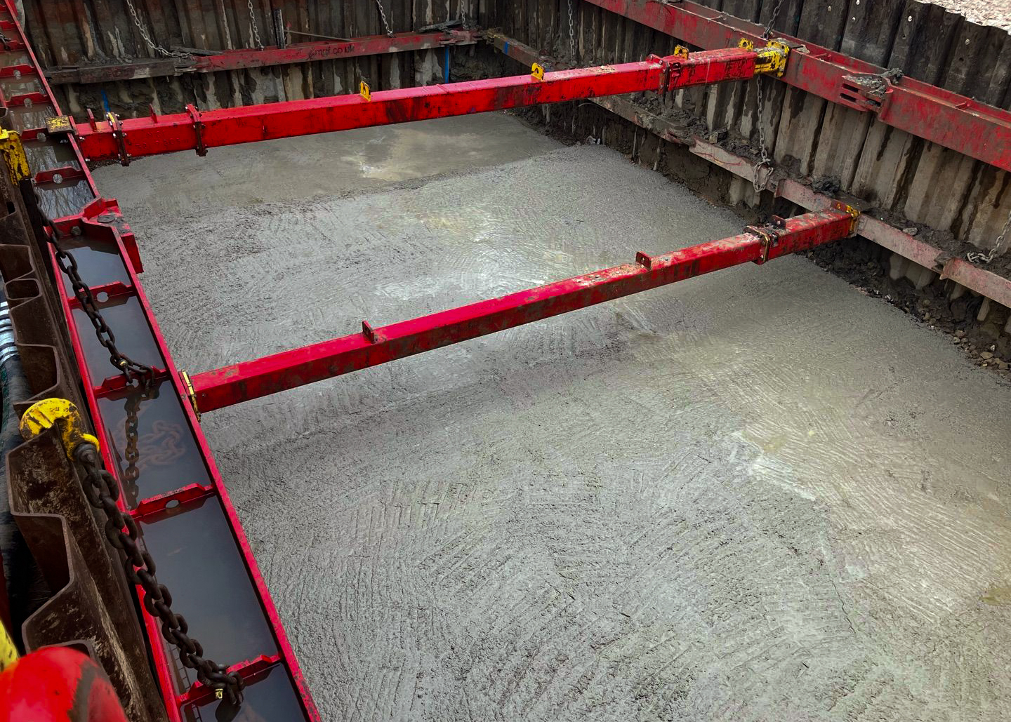
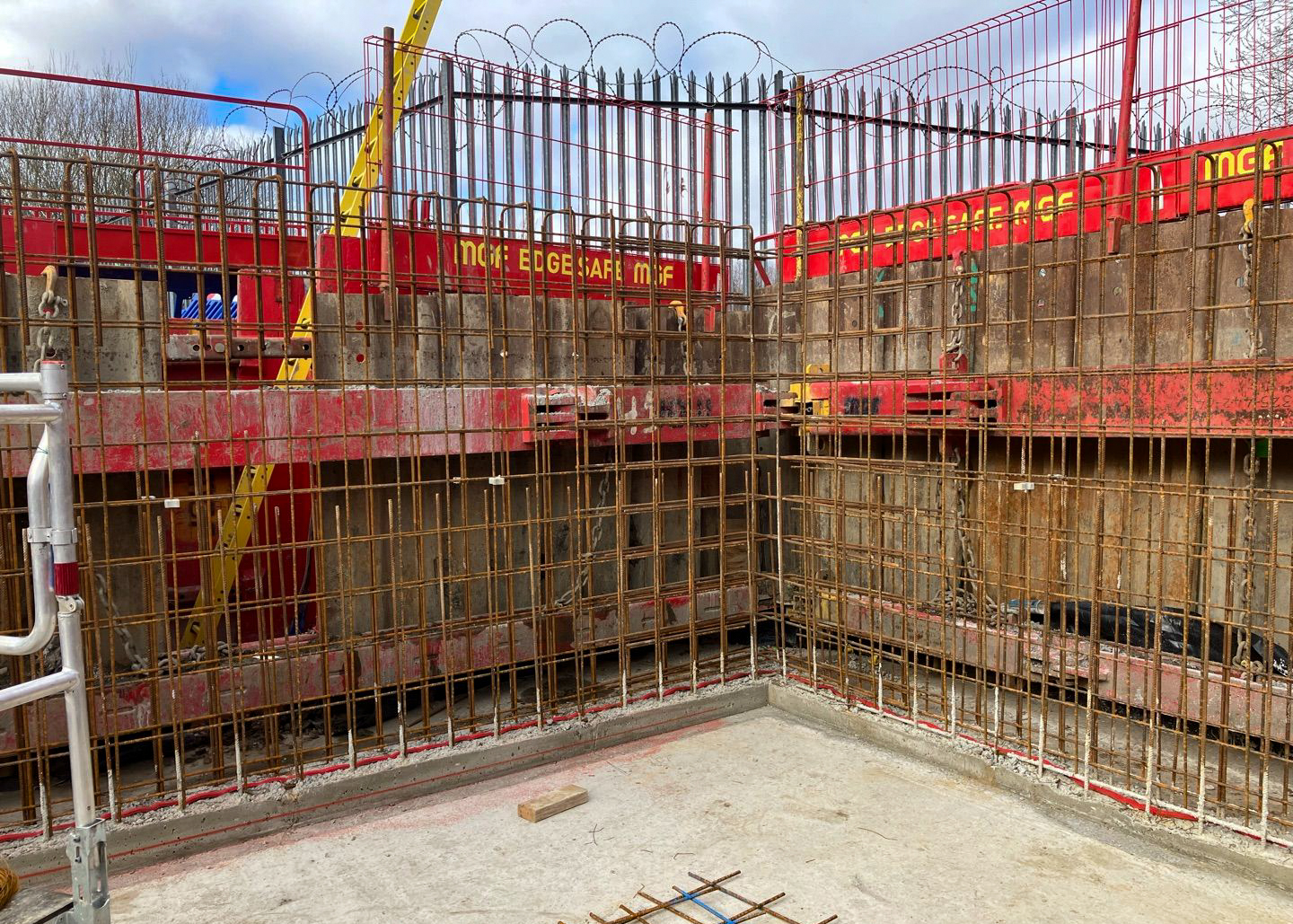
Completion of these two phases allowed Stonbury to begin the excavation works, increasing the ground depth to the correct level for the new tank. We then demolished demolition the redundant humus tank before installing the shuttering and steelwork to form the new concrete base and washout channel. When concrete had cured, shuttering was removed and the steel reinforcement for the concrete walls were installed by sub-contract steel fixers. before installing the shuttering to form the new walls. Concrete was cast in situ using a concrete pump delivered to site by MGF Ltd with the correct bracings.
Once the construction of the new concrete tank was competed, drainage was installed. First, the sump drain between the new storm tank (Storm Tank No. 3) and the existing Storm Tank No.1A were installed and flap valves were fitted in Storm Tank No.1A (during dry weather conditions), with tankers and pumps on standby to remove unforeseen storm flows.
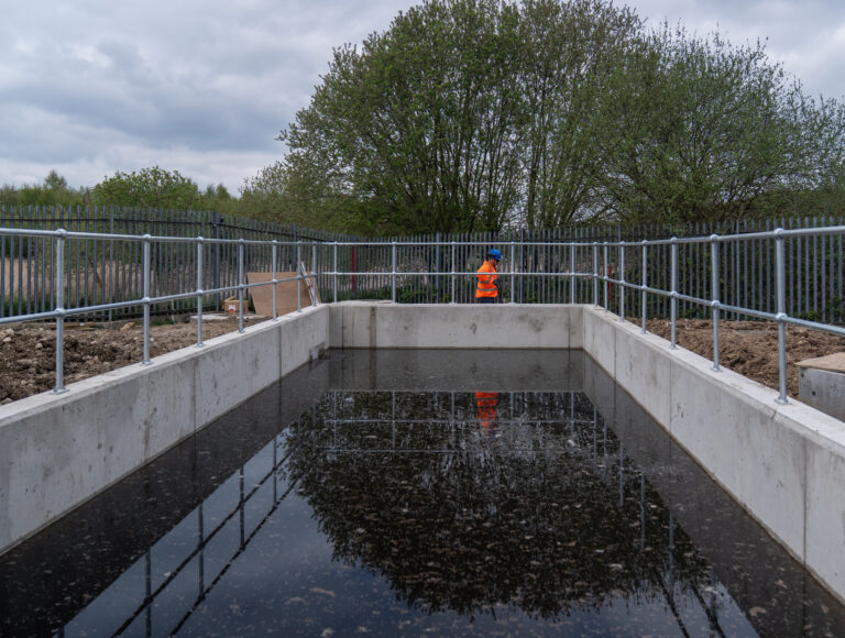
Core drilling took place to allow for the new inlet pipework to be installed from the inlet chamber. The new pipework was cast in with concrete and a Hydrotite Waterbar around the pipe and cored hole. A second core hole was made to accommodate the overflow pipework from the new tank to the overflow outlet chamber. A drop test was carried out to identify any points of egress, which verified that the new tank was watertight.
The final stage was the MEICA installation, which was supported by CEMA who installed the ultrasonic level probe and spill-to-river alarm system.
The new storm tank was brought online by switching flows to enable the tank to receive incoming stormwater. An O&M manual was issued to operations (to be stored in the control building) and all operational staff were invited to attend a short training event on the new storm arrangement, held on-site.
The Carbon Reduction Curve
A key component in aligning Stonbury’s processes with the sector’s strategy to become carbon neutral is to identify the potential for carbon reduction in all projects. Guided by the Carbon Reduction Curve, Stonbury worked with their client from the design stage to inform the design and explore lower-carbon solutions.
The Carbon Reduction Curve represents a carbon reduction hierarchy across the lifecycle of a project, from planning to operation. The curve shows the greatest opportunities to reduce carbon early in the process during the planning and design stages, where strategic decisions can avoid or minimise carbon-intensive outcomes. The hierarchy promotes a ‘build nothing’ to ‘build efficiently’ approach, where building nothing may be achieved through better asset maintenance, ‘building less’ is achieved through refurbishing existing assets, ‘build clever’ uses green alternatives if new asset creation is necessary, and ‘build efficiently’ utilises low-carbon construction methods and sustainable design features to reduce both embodied and operational emissions.
Initially, a design proposal for a lagoon was explored to ‘build less’ by eliminating the need to construct a tank. However, calculations proved that the available site footprint would not be large enough to accommodate the surface capacity a lagoon would require. Therefore, the final design consisted of a new concrete tank, built ‘efficiently’ to drive down carbon within the build phase and throughout the asset’s lifespan. These measures are featured in the Sustainability section.
The new tank was designed to be installed alongside the existing stormwater tanks on-site, making use of existing space available, plumbed into the existing pipework and utilise the existing outflow. By using exiting duct routes to carry the ultrasonic transducer cable to the control room, the design saved approximately 100m of new ducting, providing a carbon and cost saving for the client.
Designing the tank to work with the existing tanks using gravity removed the need for energy-intensive pump installations. All four tanks were designed to work together, gravity feeding overflows until all were full, and stormwater could overspill into the nearby waterbody. The drainage point on the new tank was designed to be controlled by an actuator, so once flows cease, all remaining water in the tank flushes back through the inlet works, emptying the tank and feeding water back into the processing works. Space for the new tank would be created by demolishing two redundant concrete humus tanks that have been out of service for some time.
The level monitoring and spill-to-river alarm was integrated through an existing programmable logic controller (PLC) and a new mimic page was created on the human-machine interface (HMI) to include the new storm tank.
Challenges
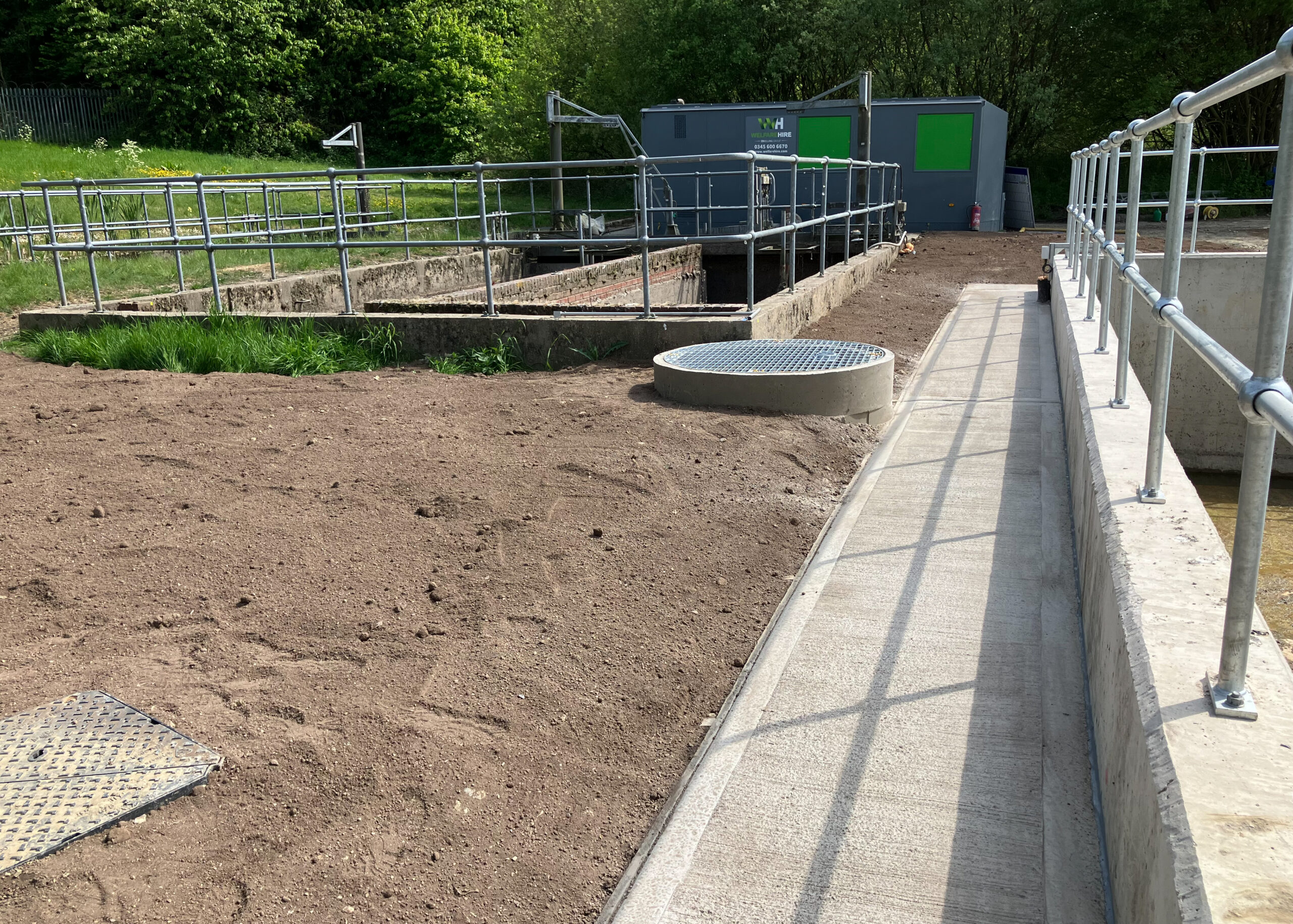
The tank’s construction presented some challenges which were overcome in a way that demonstrated Stonbury’s commitment to environmentally sound and safe practices. The most prominent challenge was the restricted space on the site, in particular, building in this small area while working around live assets and interlinking them.
To manage working in a confined area, pedestrian walkways were put in place to segregate pedestrian-plant interface; Herras fencing was erected around the work area and special routes were made for YW site operatives to gain access to live equipment 24/7.
While excavating, the team discovered excessive groundwater and some redundant stormwater services under the new tank footprint. The team safely isolated these by capping the redundant pipe and diverting the existing stormwater pipe to a formed sump within the excavation. This allowed Stonbury to install pumps throughout the duration of the programme to pump the groundwater out safely.
Groundwater was then pumped away from the site into a nearby watercourse, first filtering contaminants and sediments through silt tanks prior to discharge to eliminate the risk of pollution. Throughout the programme, turbidity tests were taken on a daily basis to ensure safe levels where adhered to.
Sustainability
Addressing Stonbury’s and their clients commitment to deliver low-carbon, environmentally restorative infrastructure, each element of the project was completed using the most sustainable method practically available. These included:
- Designing the tank in accordance with the Carbon Reduction Curve, which led to the most carbon-efficient design that was practical for the site.
- Reuse of aggregate materials produced by demolition of the pre-existing tanks within the formation for the base ofthe new tank.
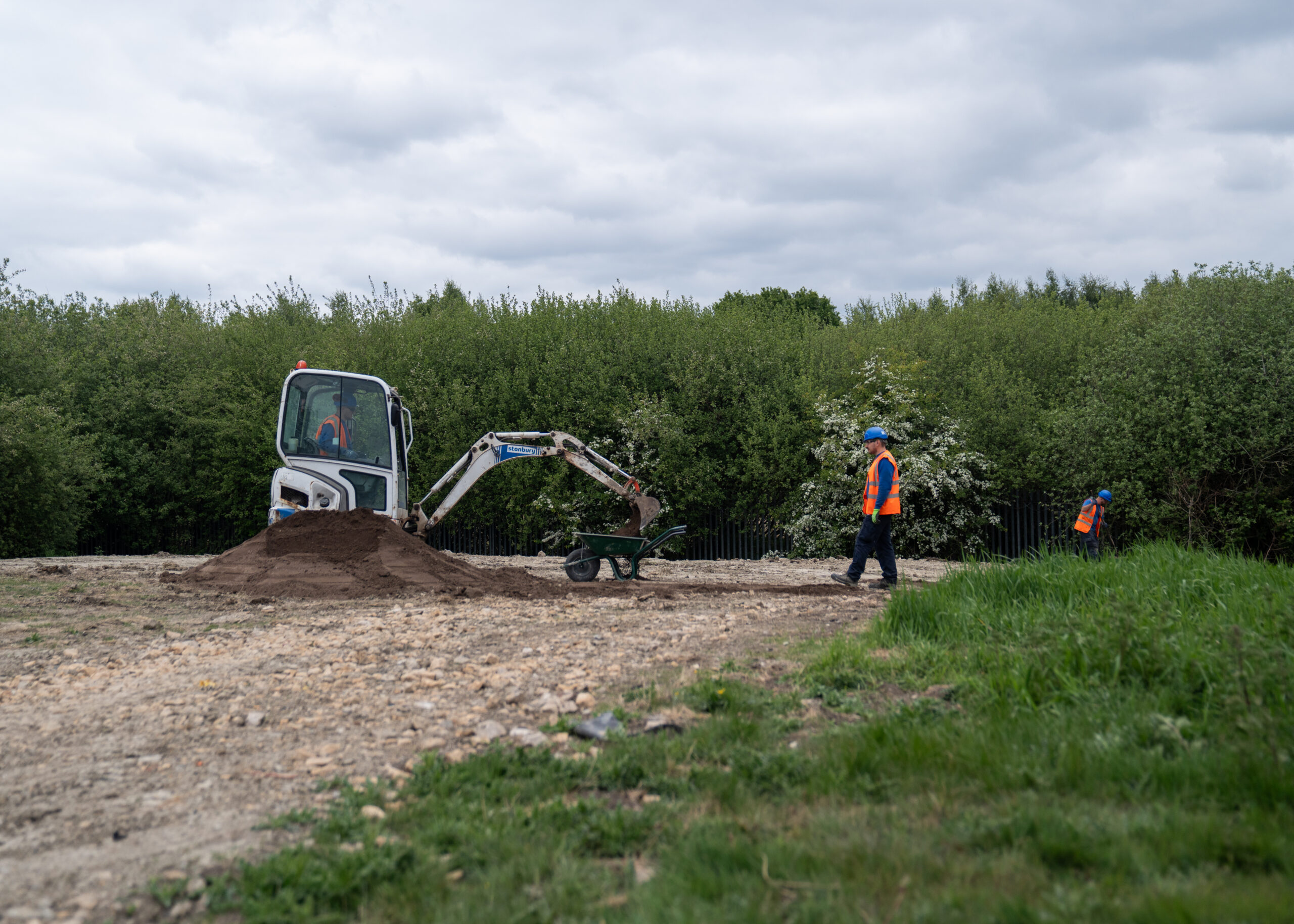
- All excavated materials were kept on-site for landscaping.
- Minimising on-site waste.
- Minimising fuel usage by ensuring pumps were switched off when not required.
To achieve sustainability objectives, the project team prioritised the use of hydrotreated vegetable oil (HVO) fuel in all machinery and established an eco-welfare unit for staff breaks. To achieve biodiversity new gain and improve the habitat potential of the site, the reinstatement involved re-seeding grass areas with a mix that supports invertebrates.
During the excavation dewatering process, groundwater was passed through a settlement tank that was regularly cleaned toremove settled solids, and through a sediment filtration sock to ensure it could be discharged in an environmentally safe manner.
Conclusion
The new stormwater storage tank spatially compliments the existing access and tank for client operations and has enabled the treatment works to retain significantly more stormwater onsite to process after storm events. This increased capacity will help prevent untreated overspills into the adjacent site ponds, improving water quality both locally and within the wider catchment. The project marks a significant contribution to their clients’ action to reduce storm overflow use and safeguard water quality throughout the county’s waterways.